| |
 Учет внутренних цепей пина (от шарика BGA до кристалла) Учет внутренних цепей пина (от шарика BGA до кристалла), Оптимальное выравнивание длин цепей памяти DDR |
|
|
|
|
 Dec 1 2006, 13:02 Dec 1 2006, 13:02
|
Знающий

Группа: Свой
Сообщений: 618
Регистрация: 7-12-04
Из: Новосибирск
Пользователь №: 1 375

|
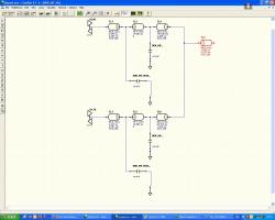
Цитата(fill @ Dec 1 2006, 15:11)  Сделайте экспорт цепи в LineSim и увидите как HL воспринимает ПО. Также посмотрите http://www.megratec.ru/data/ftp/video_tuto...a_Modeling1.swfНе могу получить как у вас картинку, у меня ПО представлена как емкость. Картинка не суть, важнее то что ПО не просто емкость а две емкости и линия передачи, со временем распространения 15пс. Получается что мои рассуждения не совсем верны. И тогда совсем не понятны рекомендации по разводке DDR2, с требованиями на 24-50 mil. 25mil я могу легко набрать конфигурацией платы (плюс осложнение в том что тексас не предоставляет IBIS файл с интерфейсом DDR2, говорят делай как в рекомдациях и будет счастье).
Эскизы прикрепленных изображений
|
|
|
|
|
|
|
|
Dec 2 2006, 09:25
|
Знающий
Группа: Свой
Сообщений: 618
Регистрация: 7-12-04
Из: Новосибирск
Пользователь №: 1 375
|
Под картинкой я имел в виду изображение на free cell based листе. У вас на нем нарисовано именно ПО. А про картинку со слоями, она у меня есть. пять много думал и читал (черную магию, том два). Вот что взято из доки на HL_via: Цитата The accuracy of the electrical model HyperLynx creates for radial waveguides, especially for its inductance predictions, depends on how well the board design observes the following assumptions:
All return current transitioning from plane-to-plane moves through the distributed capacitance of the dielectric separating the planes
No return current flows through nearby decoupling capacitors
No return current flows through stitching vias
The above assumptions are reasonable for the following board properties:
Decoupling capacitors are not placed very near the via
Or
Decoupling capacitors are placed very near the via, but the signal frequencies are sufficiently high that the capacitors do not decouple effectively, due to their parasitic inductances. This condition might happen for signaling frequencies above 400MHz or so.
The plane-to-plane separation is thin. This might happen when you try to maximize plane-to-plane capacitance to compensate for the failure of decoupling capacitors.
The above assumptions may not be so good for the following board properties:
A decoupling capacitor is placed very near the via, and the capacitor is connected or mounted in such a way that its impedance is low for the signal frequencies of interest. A decoupling capacitor might be located near the via accidentally or deliberately in order to "bypass" the via.
A stitching via is placed very near the via. This is possible only when the two planes are at the same DC voltage.
The plane-to-plane separation is thick, for example >20 mils. In this case, the via electrical model overestimates the via inductance by assuming the current flowing through the dielectric is very widely distributed, but it is likely to find a capacitor or stitching via somewhere nearby to pass through. Note, however, that even a nearby decoupling capacitor may not function effectively at higher signal frequencies. Если не трудно, посмотрите в HL7.7 раздел про модель ПО, она отличается от процитированой мной модели в HL7.5? Как раз мой случай не проходит. У меня два слоя земли на ПП, они соеденены ПО со слоями земли в корпусе микросхемы BGA. И на самой ПП много соединений между слоями. В моем случае поведение ПО чисто емкостное, а оченка HL весьма завышает индуктивность. Для себя решил что ПО в длину цепи включать не буду.
|
|
|
|
|
|
|
|
Dec 5 2006, 12:44
|

Гуру
Группа: Модераторы
Сообщений: 4 361
Регистрация: 17-08-04
Из: КП Две Поляны
Пользователь №: 512
|
Physical Structure of Vias
Vias are often used to connect traces or pins on one PCB stackup layer to traces or pins on another, usually less congested, layer. There are several type of vias:
Through-hole— Extends all the way through the board.
Blind— Formed when only one end of the via is visible on the board surface.
Buried— Formed when neither end of the via is visible on the board surface.
Microvia— Miniature via that typically goes through only a few surface layers of the board. Microvias do not change reference planes, do not have pads, and pass through only very thin stackup layers. Because microvias do not have pads, they help route traces to packages with closely-spaced pins.
Figure 15‑1 shows the physical structure of a through-hole via on a board with four signal layers (S1-S4) and two power plane layers (G1-G2).
Figure 15‑1. Example Physical Structure of a Through-Hole Via
The barrel, or tube, is the central part of the via. It is created by drilling a hole through the board and plating its walls, or filling the hole entirely, with copper or another conductive material. For microvias, the hole is created by plasma-based, laser-based, or other processes.
Circular pads are often used to connect the barrel to traces on signal layers. Pads are sometimes removed from vias transmitting differential signals.
Antipads, or annular clearances, are used to avoid connections with the poured power and ground layers.
The layer span is the outermost pair of metal layers the via connects to or passes through. In Figure 15‑1, the layer span is S1-S4, even though no traces connect to the barrel.
A stub is any portion of the via that is not used to transmit signals on the selected net. Stubs are formed when the barrel extends beyond the signal layers connecting to the via. In Figure 15‑1, a stub is formed by the via passing through layers G2 and S4 while traces connect only to layers S1 and S3.
Electrical Modeling Overview
The Via Visualizer displays the electrical model used to simulate the selected via. HyperLynx creates the electrical model by decomposing the physical via model into a set of individual physical sections, converts each physical section into an electrical model, and then builds a composite electrical model from the individual models.
Vias are treated differentially for via pairs whose nets exceed the crosstalk threshold. The Via Visualizer displays both differential vias at the same time.
For very high frequency signals, stubs can be troublesome due to their resonant properties. HyperLynx models via stubs with capacitances because it assumes the signal wavelength is greater than the stub length. The Via Visualizer reports the existence of via stubs.
Via discontinuity occurs when the average via impedance is significantly different from the impedance of any of the connected traces. The Via Visualizer reports the existence of discontinuities caused by via impedance.
Decomposing Vias Into Individual Physical Sections
As a via passes through a high-speed PCB stackup, it passes through various signal and plane layers. See Figure 15‑2. A new via section is created each time any of the following conditions is true:
The via encounters a plane layer. The new via section persists until the next plane layer is reached. For example, section 1 consists of the via section extending from layer S1 to layer G1.
The via passes through the thin plane layer. For example, section 2 consists of the via section extending within layer G1.l
Figure 15‑2. Via Sections When Traces on Layers S1 and S4 Connect to Barrel
Additional via sections are created when more than two traces connect to the barrel or when a trace not on the top or bottom layer connects to the barrel. In these cases, a new via section is created when the via passes through a signal layer that connects to the barrel.
Once the via is decomposed into physical sections, HyperLynx creates an electrical model for each section.
Modeling Ambiguity for Widely-Spaced Radial Waveguides
Section 3 in Figure 15‑2 consists of the via section lying between power plane layers G1 and G2. When layers S2 and S3 do not connect to traces, the geometry of the via and power planes form a widely spaced radial waveguide.
The accuracy of the electrical model HyperLynx creates for radial waveguides, especially for its inductance predictions, depends on how well the board design observes the following assumptions:
All return current transitioning from plane-to-plane moves through the distributed capacitance of the dielectric separating the planes
No return current flows through nearby decoupling capacitors
No return current flows through stitching vias
The above assumptions are reasonable for the following board properties:
Decoupling capacitors are not placed very near the via
Or
Decoupling capacitors are placed very near the via, but the signal frequencies are sufficiently high that the capacitors do not decouple effectively, due to their parasitic inductances. This condition might happen for signaling frequencies above 400MHz or so.
The plane-to-plane separation is thin. This might happen when you try to maximize plane-to-plane capacitance to compensate for the failure of decoupling capacitors.
The above assumptions may not be so good for the following board properties:
A decoupling capacitor is placed very near the via, and the capacitor is connected or mounted in such a way that its impedance is low for the signal frequencies of interest. A decoupling capacitor might be located near the via accidentally or deliberately in order to "bypass" the via.
A stitching via is placed very near the via. This is possible only when the two planes are at the same DC voltage.
The plane-to-plane separation is thick, for example >20 mils. In this case, the via electrical model overestimates the via inductance by assuming the current flowing through the dielectric is very widely distributed, but it is likely to find a capacitor or stitching via somewhere nearby to pass through. Note, however, that even a nearby decoupling capacitor may not function effectively at higher signal frequencies.
Tip: If a via violates one or more of the assumptions above, the resulting model is conservative, that is the via inductance is exaggerated. BoardSim should almost never claim that a via is OK when it is not; it may sometimes warn about a via that is acceptable due to nearby bypassing, and so on.
Modeling Ambiguity for Differential Vias
The electrical model HyperLynx creates for differential vias is optimized for differential signaling. If the model is driven by common mode signaling, it will probably underestimate inductance.
Common mode signaling can occur when you drive both differential pins in the same direction or if the driver model has highly asymmetric rising and falling edge rates. Also, differential signals on the board might contain some common mode content. However, well-designed differential pairs should carry very little common-mode content.
Building the Via Simulation Model
The L and C for the electrical models representing the via sections are blended together into an equivalent transmission line. However, the pad to plane capacitance for the signal entry and exit trace layers is excluded from blending and is added to the transmission line model as lumped capacitors connected to ground.
Tip: Since vias are electrically short compared to the primary wavelengths present in even very-high-speed digital signals, the transmission-line representation is just as accurate as a pure lumped model.
For vias that connect to three or more traces, additional equivalent transmission lines are created so that every trace connecting to the barrel connects to a transmission line in the simulation model.
Via Stub Capacitance
If a via contains a stub, its stub capacitance is added in the Via Visualizer to the lumped capacitor representing the via entry- or exit-layer pad capacitance. Therefore, although it may not appear as though the stub is modeled, it is because its effect is mixed with that of the entry/exit capacitance.
PS. Там еще много чего написанно. Вы видео посмотрели? Там же показанно как теперь добавляются\изменяются ПО в LineSim.
--------------------
Чем больше познаю, тем больше понимаю ... насколько мало я все таки знаю. www.megratec.ru |
|
|
|
|
|
|
|
 Jan 28 2007, 20:45 Jan 28 2007, 20:45
|

embarrassed systems engineer
Группа: Свой
Сообщений: 1 083
Регистрация: 24-10-05
Из: Осокорки
Пользователь №: 10 038
|
"Чем дальше в лес, тем толще партизаны" Моделировал цикл чтения DDR с применением модели для чипов от Микрон. Получил в HL, к примеру Min Rise Delay 150ps и Max Rise Delay 250ps. Slew Rate полядка 3V/ns. Выровнял часть byte lanes на примерно одинаковую задержку по отчету batch analyse в HL. И тут решил попробовать моделировать чипы от Samsung. Ой... Они slew rate обеспечивают на уровне 1V/ns. Нет, все ОК, дерейтинг еще делать не надо, и с отражениями получше. Но блин, Min Rise Delay 150ps, и Max Rise Delay 500ps. А борьба то шла чтобы разброс всех сигналов в 150ps уложить. Как это можно сделать для сигналов с фронтами >300ps ума не приложу  С другой стороны, что-то мне подсказывает что единственный банк DDR, от известного бренда, и на расстоянии 1200 милс от процессора работать будет прекрасно. Но как в этом убедиться с помощью моделирования? Может я неверно Min/Max Rise/Fall Delay интерпретирую? Терминаторы на VTT - 56 Ом, Rs - 27 Ом. Также выходит, что выравнивать по задержкам можно только для какого-то одного строго определенного чипа. Если его параметры "уезжают", то все выравнивание - "до лампочки".
|
|
|
|
|
|
2 чел. читают эту тему (гостей: 2, скрытых пользователей: 0)
Пользователей: 0

|
|
|