Вот что говорит стандарт IPC-7351 (February 2005) (L)_open.pdf:
3.4.4 Fiducial Marks A fiducial mark is a printed artwork
feature created in the same process as the circuit artwork
for optical recognition systems. The fiducial and a
circuit pattern artwork must be etched in the same step.
The fiducial marks provide common datum points for all
steps in the assembly process. This allows each piece of
equipment used for assembly to accurately locate the circuit
pattern. There are two types of fiducial marks.
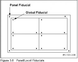
3.4.4.1 Panel and Global Fiducials Global fiducial
marks are used to locate the position of all circuit features
on an individual board. When a multi-image circuit is processed
in panel form, the global fiducials are referred to as
panel fiducials (see Figure 3-8).
A minimum of two global fiducial marks is required for
correction of offsets (x and y position) and rotational offsets
(theta position). These should be located diagonally
opposite and as far apart as possible on the circuit or panel.
A minimum of three fiducial marks is required for correction
of nonlinear distortions (scaling, stretch and twist).
These should be located in a triangular position as far apart
as possible on the circuit or panel.
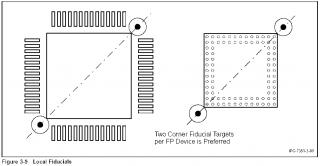
3.4.4.2 Local Fiducials Local fiducial marks are used to
locate the position of an individual component requiring
more precise placement.
A minimum of two local fiducial marks are required for
correction of translational offsets (x and y position) and
rotational offsets (theta position). This can be two marks
located diagonally opposed within or outside the perimeter
of the land pattern (see Figure 3-9).
It is good design practice to locate global or panel fiducials
in a three-point grid-based datum system as shown in Figure
3-10. The first fiducial is located at the 0-0 location.
The second and third fiducials are located in the X and Y
directions from 0-0 in the positive quadrant. The global
fiducials should be located on the top and bottom layers of
all printed boards that contain surface mount as well as
through-hole components since even through-hole assembly
systems are beginning to utilize vision alignment systems.
All fine pitch components should have two local fiducial
systems designed into the component land pattern to insure
that enough fiducials are available every time the component
is placed, removed and/or replaced on the board. All
fiducials should have a soldermask opening large enough to
keep the optical target absolutely free of soldermask. If
soldermask should get onto the optical target, some vision
alignment systems may be compromised due to insufficient
contrast at the target site.
If space is limited, one may be able to share a fiducial from
an adjacent component within the location constraint (see
Figure 3-10).
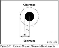
3.4.4.3 Size and Shape of Fiducial The optimum fiducial
mark is a solid filled circle. The preferred diameter of
the fiducial mark is 1.0 mm. The maximum diameter of the
mark is 3.0 mm. Fiducial marks should not vary in size on
the same PCB more than 25 μm. A clear area devoid of any
other circuit features or markings shall exist around the
fiducial mark. The minimum size of the clear area shall be
equal to twice the radius of the mark (see Figure 3-11).
3.4.4.4 Zonal Fiducials To ensure the accurate placement
of multiple surface mount components that are not
near ‘component specific local fiducials’ or ‘global fiducials’,
additional ‘zonal fiducial targets’ may be placed
within a zone or an area of the board assembly to compensate
for board dimensional stability.


 Apr 4 2006, 08:37