Цитата(AlexKLm @ Oct 12 2008, 15:16)

I do not understand your idea with groud-plane (antenna?). I propose the following decision:

Part of enargy will be directed to waveguid. But please remember, that the frequency of the oscillator will depend of the load of the waveguid. This is why the better way is to make coupling through probes or loops taking energy from oscillator output, when the oscillator's resonance system is buffered (as normally, i hope).
First, you may write in Russian. I just do not have Cyrillic keybord, so i write in english.
I wish to tell you what was the trigger for such an "old fassion" attempt to build a cavity oscillator.
The problem is, that if you need low noise LO at elevated frequencies, typically one goes for CRO or a DRO:
1. CRO is pretty simple to manage exept at frequencies above 2GHz. There, the length of the resonator begins to be too small to have any appreciable Q, so you revert to OVERTONE oscillator. Its OK, as long as you manage to suppress the obvious tendency of such an oscillator to jump back to fundamental tone generation. But it is still a nuisance.
2. If we are working above 3-4GHz, we go for DRO. Here it all very simple, except the need for special glue for the pill (to avoid Q reduction of the pill, and work on wide temperature range without weakening).
A very big trouble, is that the DR pill is built from such a hard ceramic material, that it cannot be trimmed with any tools readily available to "normal RF engineer". Using a metallic or dielectric tuner, any DRO can be trimmed, perhaps +-250MHz, before severe Q degradation. You want a new frequency beyond that? Order a new batch of pills! So, while the pills themselves may be low cost at large quantities, below 20-30 oscillators, their cost is prohibitive.
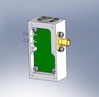
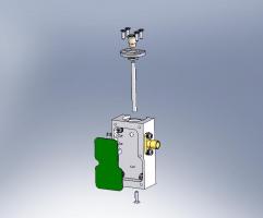
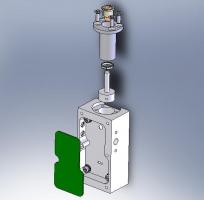
A possible solution i seek is to revert to good old cavity configuration. But no waveguides, please! Have any adea how the 2.7GHz or 4.5GHz waveguide looks like? An elefant! Going thru various literature, including the Rhea book- "Microwave oscillator design and computer simulation", reading about HP8640 VHF-UHF instrument and dismounting vatious Phase-Locked bricks like California Microwave and CTT, i noticed a cavity L band oscillators with SRD multiplier and "cavity" combline filters for the output frequency. All is well, except they use 1/2-Lambda cavity and thru-hole packaged transistors, 70's style. The mount of those transistors as well as the fine tuning of their coupling to the cavity is labor intensive and very awkward to tune and accomplish. The big issue, is WHAT TYPE OF CAVITY to use, and HOW TO COUPLE the transistor and the Varicap to the cavity. I decided to try and go for 1/4-Lambda COAXIAL cavity (actually, it will be 10% shorter than that) and easy modern SMD technology with MAGNETIC slot coupling of the microstrip to cavity via a narroe slot. The design in the pictures still uses probe coupling of the Varicap, but i may change this to slot later, if the experiment will be succesful. I wanted to know whether of any other experienced folks around the globe ever tried such a design.


 Oct 9 2008, 14:28